
Assembly of a Gripper for a Wall-mounting Robot
Main Sector of Application
Manufacturing of robots and machines
Potential Sector/s of Application
Manufacturing of other types of equipment
Solutions for sectors like construction, aviation, food
and medical areas
Description of the Experiment
Precizika Metal is a typical SME company that is evolving from being a component supplier to delivering full solutions. This implies an increasing need to deliver fully assembled products to clients. Due to the lack of qualified workforce (or at least being a challenge to find qualified workers) and due to a constant need to be more flexible but also more efficient, methods to automate the current assembly processes that are still performed manually have to be developed.
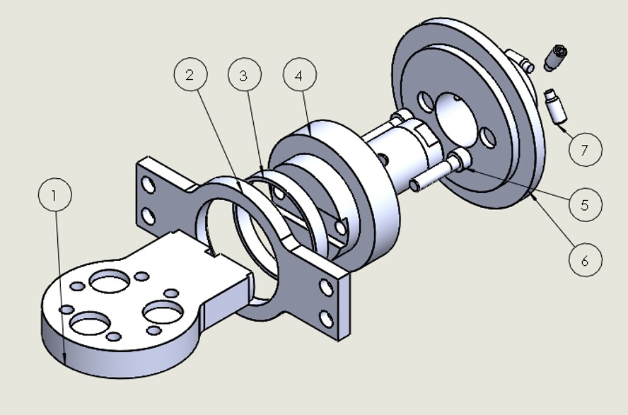
The Precizika Metal use case consists of the assembly of a part of a glass mounting gripper. Assembly parts enter the cell on a pallet situated on a trolley equipped with a plug and produce (PnP) connector. In this experiment, a total of three PnP trolleys are used. The assembly procedure roughly consists of the following steps:
- Robot 1 grasps the pitch to roll flange (part no. 1) and the break shaft (part no. 4) using a double gripper. It then positions the shaft into the pneumatic press.
- Robot 2 uses a double gripper to grasp the roll side support (part no. 2) and the bearing bushing (part no. 3). Meanwhile robot 1 positions the flange in the fixture, i.e. vice.
- Robot 2 centers the bushing and support on the shaft positioned in the press.
- The press is actuated. While an active press could be used, a hand-operated press was used in ReconCell. One of the robots moved the handle to activate the press.
- Robot 1 picks up the assembled parts from the press and positions them on top of the flange.
- While robot 2 picks up the screws (part no. 5) and positions them appropriately, robot 1 changes its tool for the screwdriver. After it screws both screws, robot 2 changes the driver's screw bit.
- Robot 2 attaches the three finger gripper and picks up the kendrion (part no. 7) with screws (part no. 8) prepared in the holes. As the kendrion has three screw positions on the side, the rotation is important. In our experiment, the rotation of the kendrion on the trolley was determined using visual pose localization. Robot 2 positions the kendrion on top of the assembled pieces.
- While robot 2 is still holding the kendrion in place, robot 1 screws in the first screw. As all screw positions cannot be reached from the limited workspace of the robot, alternative solution was needed. A passive rotation table was used to attach the vice to the trolley. As the brakes on the rotation table were released, robot 1 was able to rotate the vice with all the assembled pieces while holding the kendrion. After rotation for 120°, robot 1 screw motion was repeated. After another rotation, the last screw was attached.
- In the last step, the vice is opened and the assembled part of a glass mounting gripper is positioned back on the trolley.
Main Objectives of the Experiment
While a lot of Precizika Metal use case aspects called for a non classic approach to automation, hence some innovative approaches had to be specially developed for this experiment. Both aspects presented here are related to screwing. The first aspect tackles the improvement of the screw mechanism and the second one solves the problem of limited workspace by introducing a passive rotation table.
Although the screw mechanism developed for the Elvez use case has already been upgraded for the Logicdata experiment, further improvement were needed. As can be seen in the final implementation video, the whole screw mechanism extension was upgraded. Exchanging 3-D printed parts with brass parts improved stability of the screw bit and improved the precision of the top. A new design for the screw bit exchange improved the overall reliability of the robot assisted bit exchange. For more information on the screwdriver please see reconfiguration.
As the kendrion screw positions are spaced at 120° (part no. 8), they cannot be reached from the limited workspace of the robot. This is additionally limited by the overall length of the screwdriver. An expensive off-the-shelf solution would be an active rotation table. However, as one of the main paradigms of the ReconCell project are affordable solutions for SMEs, a passive rotation table was designed. The table is locked in place with three pneumatic actuated pins. When they are released the table can be rotated freely by the robot. This enabled us to reach all sides of the assembly area while keeping the costs of the hardware relatively low. The rotation table is additionally explained here
Final Results
While the assembly problem defined at the beginning of the project had to be modified, it still maintained all the representative parts. Parts were also modified to enable automatic assembly. The assembly process could have been further improved by a pneumatic press, which would allow to speed up the process. While the automated assembly solution is slower than manual labor, it makes the assembly process easier for the workers, saving the valuable human work force for decision making. This is important for Precizika Metal in order to reduce the overall costs of operation.
The reliability of the assembly was high, but failures were still occurring. The low tolerances needed for successful placing parts on other parts (e.g. bushing on support) could be more reliably achieved with upgraded (metal) gripper fingers.
The final implementation of gripper assembly in ReconCell. The workcell had been reconfigured by manually interchanging modules, like the tool rack trolley, part trolley and press trolley in order to accommodate the assembly of this product.
Final assembly & customization of drive systems and control boxes
Main Sector of Application
Electronics industry
Furniture industry
Potential Sector/s of Application
Part customization
Description of the Experiment
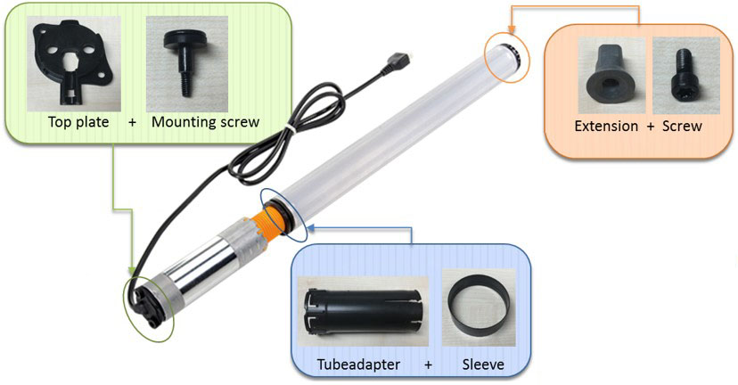
Logicdata is an innovation leader and the leading supplier in the field of motor controls, operating elements and actuator elements for electronically adjustable furniture. Their challenges are high volume products with various customization possibilities. This leads to many different product versions, based on only a few basic versions. The basic versions are produced in high volumes on specific production lines and then manually finalized before packing. The experiment implemented in ReconCell is an assembly of a slimdrive module, which is used in adjustable furniture. The Logicdata drive system, with some of the possible attachments (Figure). In this experiment we tested the applicability of the ReconCell system for final assembly & customization of drive systems. Customization far away from the customers leads to long delivery times, especially for those who are located overseas. The automated robot workcell would give the company an opportunity to do finalize the customization close to the costumer in a cost-efficient way for a whole range of products.
This experiment consists of attaching several parts to the pre-assembled drive system. The pre-assembled basic versions of the drive systems come into the cell packed in 5 in a cardboard box. The customization parts, the required tools and grippers are introduced using trolleys. The trolleys connect to the workcell using Plug and Produce (PnP) connectors and provide efficient and precise material flow. Roughly, the assembly task consists of the following steps:
- 2D visual localization is used to determine precise positions of the basic drive systems.
- Robot 2 picks up the slimdrive, puts it in the position for camera measurements and afterwards inserts it in the active assembly fixture. Meanwhile robot 1 picks up the camera to measure the orientation and distance of adjustable parts of the drive (spindle height, orientation, slimdrive height).
- Robot 1 picks up the screwing tool, while the robot 2 picks up the top plate part. As two different types of screws were used in this experiment, screwdriver expansion was upgraded. It can now exchange the screw bit so both types of screws can be picked up and screwed in.
- Robot 2 adjusts the stator rotation based on the visual measurements to fit the desired rotation at the end of assembly. After this operation has been completed, robot 2 holds the top plate in place, while robot 1 picks and screws the two required screws.
- The slimdrive is then rotated for further assembly. If the extension customization is required, robot 1 changes the screw head, robot 2 picks up the part and holds it, while robot 1 screws it onto the drive. The extension rotation is also fixed to the desired end value.
- If the tube adapter customization is required, robot 1 changes its tool and picks up the parts. It then attaches the parts to the drive system.
- After the assembly is finished, robot 2 grasps the slimdrive with the appropriate tool and places it in the appropriate packaging.
Main Objectives of the Experiment
The Logicdata use case showed the need for a robust, reliable and modular measurement system. The pre-assembled drive system is manufactured off-site and is delivered with undefined values of certain properties (e.g.: stator rotation, spindle length, ...). As these values effect certain aspects of the assembly, they need to be determined beforehand. The finished assembled product also needs to have these properties set to predefined values. The integrated visual measurement system, which uses camera-in-hand approach, showed to handle the mid-assembly measurements well and provides the needed results for assembly adaptation and final parameter settings.
The final implementation of drive assembly in ReconCell. The workcell had been reconfigured by manually interchanging modules, like the tool rack trolley, part trolley and fixture trolley in order to accommodate the assembly of this product.
Final Results
The final implementation of Logicdata use case can be seen in the video. A 30 pieces assembly test was done between 12th and 13th of September 2018 at JSI with delegates from Logicdata. The results are presented in the table. For additional explanation regarding various steps, see the assembly procedure and the final video for this use case.
| Step | Total | Percentage |
| Fitting the extension on the steel spindle failed | 18 | 60 % |
| Mounting of sleeve failed | 18 | 60 % |
| Top plate screw 2 didn’t tighten* | 10 | 33 % |
| Top plate screw 1 didn’t tighten* | 9 | 30 % |
| Screw driver didn’t fit into the next adapter | 7 | 23 % |
| Pick-up of the sleeve failed | 6 | 20 % |
| Program stopped | 5 | 17 % |
| Pulling to tube adapter over the nut insert failed | 4 | 13 % |
| Setting the distance at the extension failed | 3 | 10 % |
| Pick up of the top plate failed | 2 | 7 % |
| Mounting of tube adapter failed | 2 | 7 % |
| Emergency stop because of crash | 2 | 7 % |
| Fitting the top-plate screw in failed | 1 | 3 % |
As can be seen, the failure rate during the test was relatively high. The two most frequent failures happened during extension fitting on the spindle and while mounting the sleeve. Both of these failures can be attributed to non-precise holding of the drive. Furthermore, this non-precise holding of the drive stems from the two failures with the third and fourth most common occurrence: tightening of the top-plate screws. The drives used for this testing were rejected from the production line at Logicdata due to faulty threads for the top-plate screws. This led to failures during screwing, which in turn lead to non-precise positioning of the drive, and finally to the two errors with the highest occurrence. This issue shows the importance of pre-assembly part reliability. In order to automate the production, the parts need to have of good quality.
Other steps with a high failure percentage relate to screwing. This experiment showed the weak points of the screwdriver extension. At this stage, a 3D printed pneumatically actuated screw bit exchange system was used. For the next use cases, the screwdriver extension was redesigned and constructed from brass. This improved the reliability of the screw bit exchange and the stability of the screw bit.
Even though the experiment had high failure rates, the information gained benefited the further development in the project as well as provided important information to Logicdata about the possible automation of the production line. As weak points were determined, they can be avoided in a follow-up automation efforts.
Assembly of Automotive Lights
Main Sector of Application
Automotive industry
Potential Sector/s of Application
Manufacturing
Description of the Experiment
Company Elvez d.o.o. is the manufacturer of specialized products for the automotive industry, electrical and mechanical engineering, and white goods manufacturers. The use case implemented in the ReconCell project tackles the assembly of automotive lights. The assembly of automotive lights in Elvez is currently to a large degree done manually. Typically 8 workers are involved to realize the work in a required cycle time. The production takes place in four shifts (24/7). The current production line at Elvez consists of specially designed assembly machines, different for each light housing model. While these machines provide an assembly method with short cycle times, they are not cost efficient as they have to be designed and produced for each different light housing model. To ensure the possibility for assembly of various light housings from a family of products on a single workcell, special focus was given to the reconfiguration of housing fixtures within the cell.
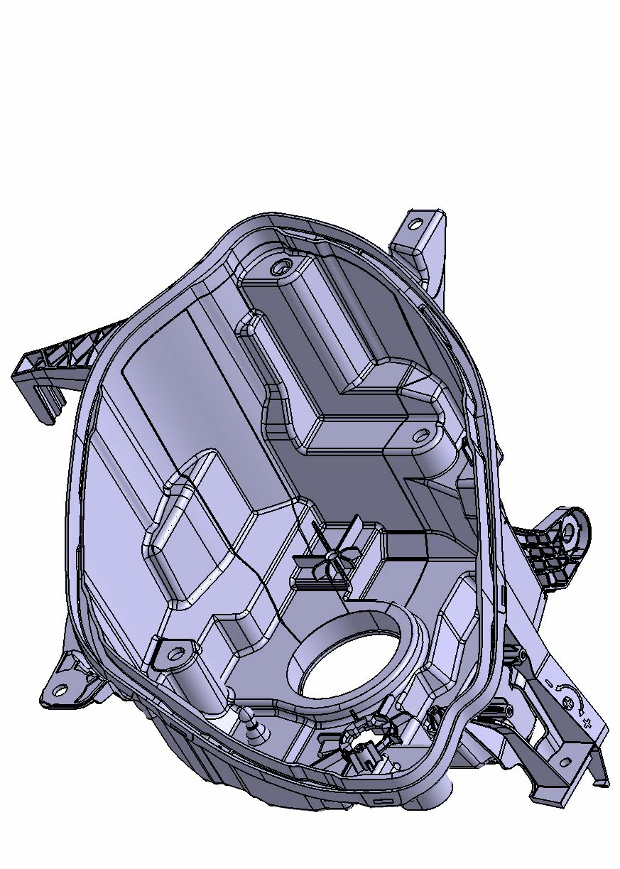
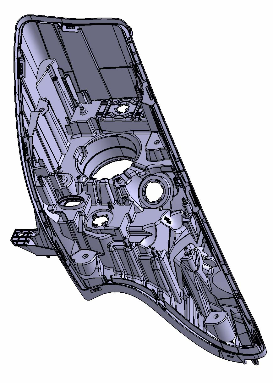
Two different light housings from the same family of products were selected for this experiment. They differ in shape and some assembly components. The two light housings, x07 and x82, can be seen in the figures. Even though the assembly procedure is slightly different for various light housings used in this experiment, the general assembly task is roughly the same. A rough description of the assembly task is given with the following steps:
- Light housings (in our experiment we used models x82 and x07) and other assembly components come into the workcell on pallets mounted on trolleys. The trolleys are connected to the workcell using Plug and Produce (PnP) connectors. The position of the assembly components can be determined using vision, so that the robots can reliably grasp the assembly components.
- Robot 1 starts the assembly by grasping the housing part (either x07 or x82). Housing parts are placed into special reconfigurable fixtures. The fixtures are based on a non-actuated Stewart platform that can be configured for a specific model of the housing. As reconfiguration can be performed by the two robots in the cell, minimal human intervention is needed.
- For the assembly of the bulb holder and LWR motor, robot 2 uses a double gripper. The x07 model requires the assembly of both LWR drive and bulb holder while the x82 model requires the assembly of the LWR drive only.
- The X07 light housing model requires the insertion of a sheet metal part that acts as a heat shield and prevents overheating of heat sensitive plastic parts. Robot 1 uses a passive magnetic gripper to pick up the heat shield and slide it in place.
- A screw needs to be inserted at this step. For automatic screwing various innovative technical possibilities (e.g. fixed or movable screwdriver with integrated, automatic screw feeding system) were examined. An of-the-shelf screwdriver was enhanced with a screw bit which enabled screw pick up and insertion.
- After finishing the assembly, the first robot grasps a camera and inspects the assembly quality control points. When the inspection is done, the robot re-equips the housing gripper and then proceeds to put the light to the final position.
By making use of the business intelligence system integrated with the ReconCell system, we will be able to show real benefits of the proposed reconfigurable assembly system from the order to delivery.
Main Objectives of the Experiment
One of the main aspect of this experiment was the automatic reconfiguration of fixture points.
When companies introduce a new production process, they do feasibility studies to estimate its profitability. Often companies (95%) take into account just the quantity of parts when the production process is in full run, but they forget that after the end of regular production, spare parts must still be produced. This means that companies must take into account that first they will be making a large number of parts, but after the end of regular production they will still need to make a smaller number of parts.
For every new automotive light (start of production), ELVEZ has to order two new assembly devices (left side, right side). After the end of production, assembly devices must not be disassembled because they are needed to manufacture spare parts. Assembly devices must therefore be stored in a company for the next 10 years. This means that company needs a lot of storage space to store these assembly devices. Production of spare parts is a low quantity production and is typically done only once per year. Assembly devices are not universal but are different from product to product.
The purpose of this experiment was to show that we can use a reconfigurable robot workcell to assemble different products, thereby alleviating the need to produce and store many different assembly devices. For example, with the same injection moulding machine, we will be able to make different headlight housings with typical structural elements for three different lights.
While the assembly procedure changes between various parts, the difficult reconfiguration aspect of this use case are the fixtures. As the two used light housing differ in shape, the cell needs to appropriately reconfigure the fixture points. As explained above, the non-actuated Stewart platforms were used to enable the required automated reconfiguration of the cell’s fixtures.
Final Results
The final implementation of Elvez use case can be seen in multiple videos on this page.
In March of 2018 a Production Part Approval Process (PPAP) test was performed at JSI with delegates from Elvez. The PPAP test is used in the automotive supply chain for establishing confidence in suppliers and their production processes.
During a 42 pieces test, quality control was performed on four crucial parts of the finalized product. The binary state of successfully insertion of the housing into the fixtures, of the LWR drive, and the bulb holder was established. More accurate measurements were performed by hand for the screw height and heat shield height, i.e. heat shield insertion. In addition visual inspection was done and results were compared to the manually determined values.
Based on the PPAP results the assembly was automotive approved. Throughout the 42 pieces test all insertions were successful. Visual inspection was collaborated by manual inspection in all executions. A report on the heat shield insertion and the screw height is attached as Appendix A. It shows that the capability machine index for both is above the threshold of Cmk > 1.33. This means the product is within tolerances and the repeatably is satisfactory.
Implementation of the X07 assembly in ReconCell.
Implementation of the X82 light housing assembly in ReconCell.
The workcell includes passive fixture modules called hexapods, that allow active reconfiguration by the robot. After assembling the first housing, the workcell autonomously reconfigures itself in order to assemble a different housing.
Assembly of airport signalization module
Main Sector of Application
Aviation industry
Potential Sector/s of Application
Manufacturing
Description of the Experiment
Ivamax is a privately owned company for engineering, consulting and production of custom made devices and solutions. Most notably, the company produces sub-assemblies for companies related to airport signalization. These lights are installed on runways, taxiways, and other places with similar function. Currently, the company performs assembly of two different types of airport signalization lights, with two new types under development. The company plans to introduce automation in order to improve quality and consistency, optimize costs, and allocate human resources to higher added value projects.
The assembled part consists of aluminium casing, transparent prisms and silicone sealant. Currently, two types of the product are assembled. The assembly process consists of insertion of the prisms into metal casings. After one prism is inserted, the procedure is repeated for the second prism. While the principle of the process itself is not complex, it involves a number of particularities that require attention. For example, transparent prisms have a complex shape, and some of their sides have notches needed for better fitting into the casing. While the original open call submission included silicon dispensing on the prisms, the use case was accepted without it due to time constraints of the project.
The overview of the assembly procedure can be stated as:- Robot 1 picks up the first prism with an appropriate gripper. If localization is needed, position and rotation of the casing is determined using vision.
- Robot 2 picks up the square/round casing using an appropriate gripper and positions it in the vice.
- Robot 1 opens the centering fingers on the prism gripper and inserts the first prism into the casing. It then picks up the second prism and inserts it in the casing.
- Robot 2 picks up the finished product and places it back to an appropriate position.
Main Objectives of the Experiment
The Ivamax use case needed specially designed vice jaws to firmly grasp both casings, different grippers for both casings, and prism grippers, the latter being the most challenging. As the prisms need to be placed in a tight space, they needed to be grasped repeatably and in a way not to collide with the casings. The grippers designed for this use case grasp the prisms with two angular fingers in a repeatable and precise fashion. In order to position them inside the casing the fingers retract, while vacuum cups hold the prism in place.
Final Results
A technical proof-of-concept for the assembly of airport signalization lights in a reconfigurable workcell was thus performed successfully. The final implementation showed that the workcell can be quickly adapted to new use cases by applying specially designed vice jaws, visual pose localization for new objects, and special grippers for positioning of objects in tight spaces.
The Ivamax use case final assembly was executed multiple times and showed a reliable implementation with no failures.
The final implementation of the round casing Ivamax experiment
The final implementation of the square casing Ivamax experiment
Mounting PCBs on a backplate
Main Sector of Application
Electronic industry
Potential Sector/s of Application
Manufacturing
Description of the Experiment
HOP Ubiquitous is offering a wide range of IoT devices and sensors for Industry 4.0 and Smart Cities, including devices for air quality monitoring, gas monitoring (calibrated and certified sensors in HOP Ubiquitous's own calibration laboratory), temperature, humidity, and noise monitoring.
HOP Ubiquitous use case consists of mounting printed circuit boards (PCBs) on a backplate. To ease the process of automation, HOP Ubiquitous proposed a solution that replaces holes and screws with simple PCB spacer supports that can be inserted in the backplate. Their partners produce a variety of IoT devices with different configurations of PCBs. The provided use case focused on three variations which include combinations of the three different PCBs: Smart Spot with Gas Expansion, Smart Spot with Battery Expansion, and all three PCBs together. Before each PCB is mounted on the backplate, spacers need to be inserted into its holes.
The assembly procedure roughly consists of the following steps:- Robot 1 picks up the backplate and positions it on the assembly plate.
- Robot 2 picks up the Smart Spot PCB using a servo gripper and holds it for mounting of the spacers. As the same fingers need to be used for all PCB, they were designed to center and hold any of the three PCBs.
- Robot 1 uses an active spacer tool to pick up and attach the four required spacers.
- Robot 2 attaches the Smart Spot PCB on an appropriate place on the backplate.
- If needed, repeat steps 2 to 4 adapted for the Gas Expansion PCB.
- If needed, repeat steps 2 to 4 adapted for the Battery Expansion PCB.
- Robot 1 picks up the finished product and moves if for visual inspection.
- Visual inspection is performed on the spacers to determine if any errors occurred during the attachment of PCBs.
- Robot 1 picks up the finished product and places it at the desired final location.
Main Objectives of the Experiment
Besides the required modularity to facilitate multiple variations of the product, this use case called for solutions regarding spacer insertion and precise grasping of various PCBs. As can be seen in the video, an active pneumatic tool was designed for spacer insertion. In order to grasp each PCB, three pneumatic grippers would be needed, as the range of pneumatic grippers is small and the PCB vary in size. To reduce the number of required pneumatic grippers, we used a servo gripper instead. Taking into account the Industry 4.0 paradigm, a Power over Ethernet servo gripper was designed. It includes a micro PC to enable connectivity and control over ROS. For more information on this gripper, please see link.
Final Results
Although the reliability of the HOP Ubiquitous use case implementation was high, failures related to spacers were not uncommon. The presence of irregularities in the PCB spacers was shown to be a limitation. Irregular or defected spacers are not placed correctly in the PCBs, which in turn causes the PCBs not to be assembled correctly. This requires a pre-assembly manual check of all the spacer by an operator. Replacing these with higher quality spacers would mean a significant improvement in the process, eliminating possible errors, improving reliability, and reducing assembly time.
The implementation shows that the workcell can be easily adapted to solve the problem of automated assembly of PCB components.
The final implementation of HOP Ubiquitous use case